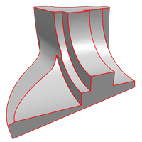
Feature lines refer to curves on a surface that help reveal and explain its geometric form. These lines denote changes—either abrupt or gradual—in the behavior of the surface and are significant to overall form. In practice, feature lines indicate to meshing algorithms which areas require careful attention to geometric details.
For CAE engineers, feature lines indicate optimal locations for element orientation, necessary refinement, and appropriate segmentation. For software engineers, these geometric markers inform preprocessing routines, curvature analysis, and feature-aware mesh generation.
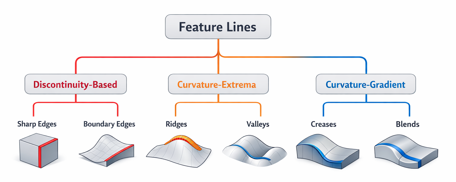
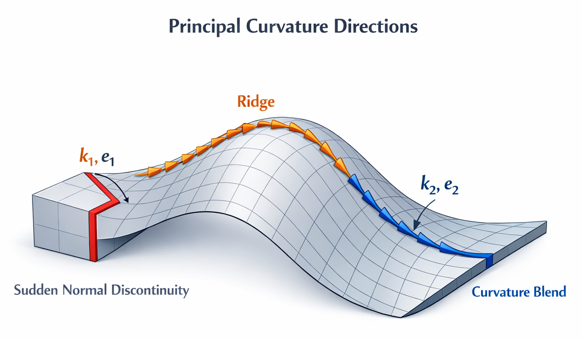
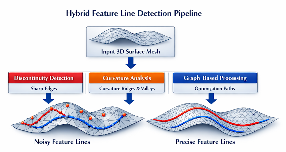
Feature lines typically arise from two main geometric phenomena:
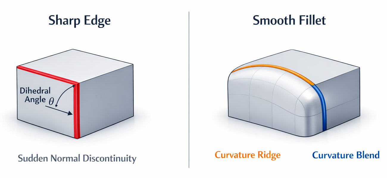
- Discontinuities in surface orientation: exemplified by sharp edges that exhibit sudden shifts in surface normal direction.
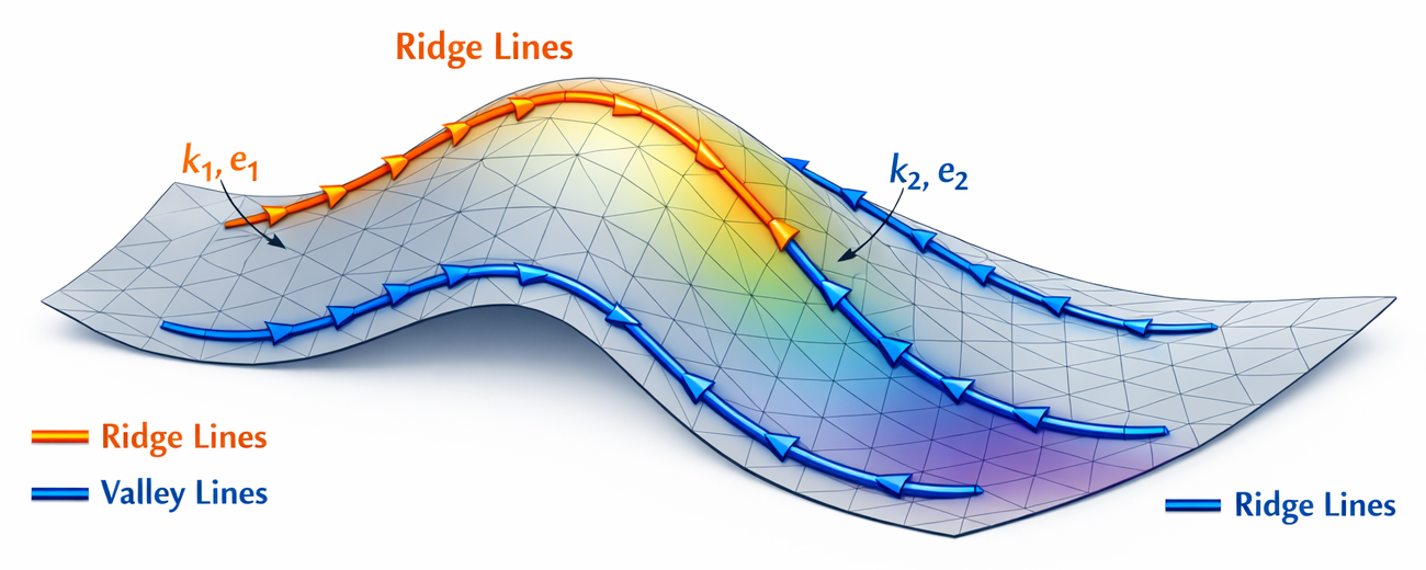
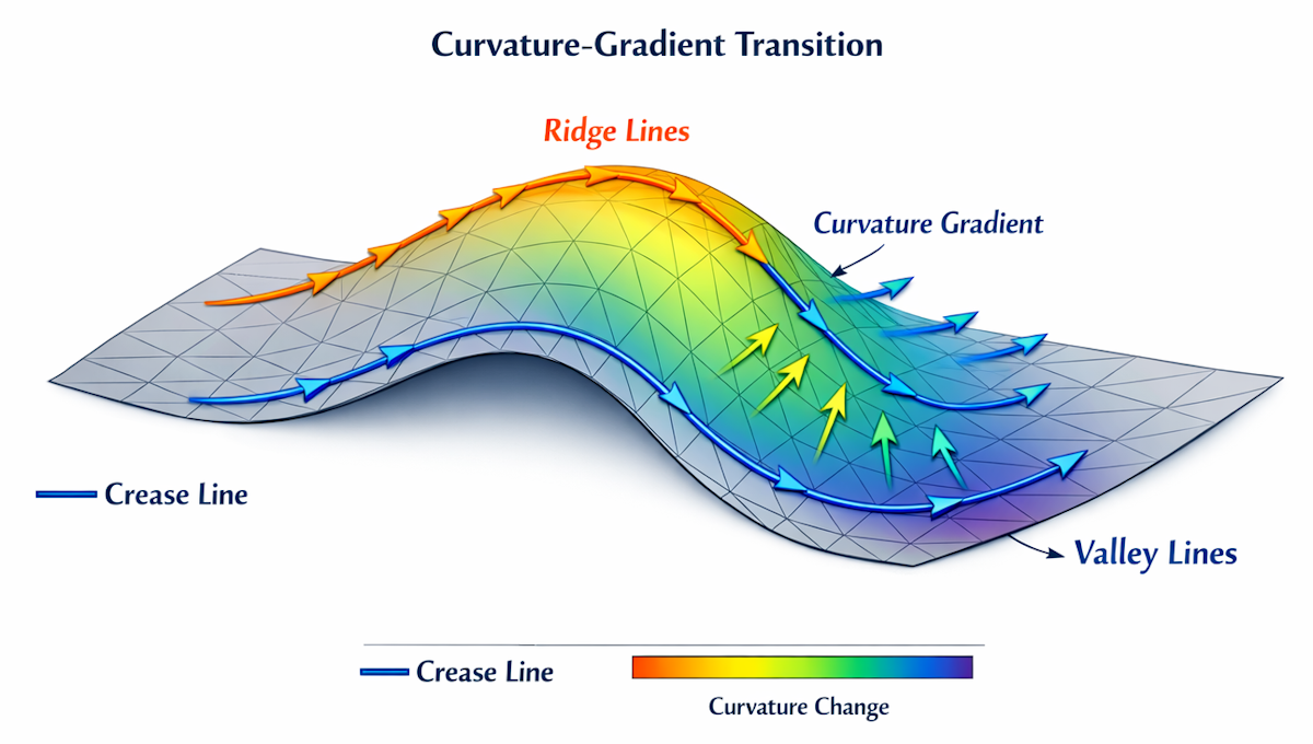
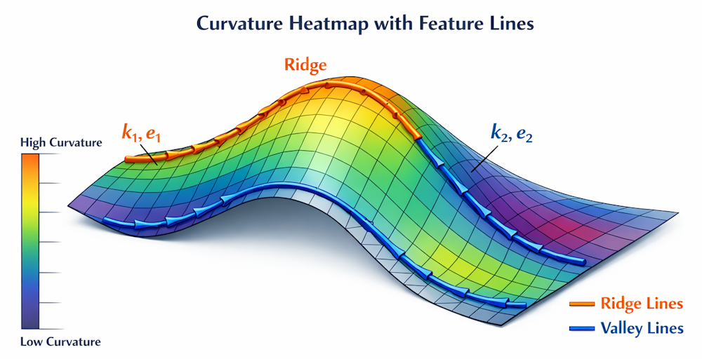
- Extrema or rapid variations in curvature: including ridges, valleys, and blends observable even on smooth CAD surfaces.
These characteristics produce curves that are both visually distinct and geometrically consequential, supplying critical structural information beyond what standard triangles or NURBS patches convey.
Feature lines serve three primary functions:
- Clarifying shape through emphasis on transitions, bends, and functional elements.
- Dividing the surface into regions conducive to consistent meshing.
- Informing downstream processes, such as segmentation, refinement, boundary layer formation, and solver stabilization.
Feature lines connect geometry and mesh, making surfaces clear and ready for quality meshing.